
Custom Configuration of the Touch Point in the nano EDGE ENGINE controllers
Lesson Progress
0% Complete
This section presents how to add a device to the Modbus network in the nano EDGE ENGINE controllers and how to read basic parameters from the Touch Point using Modbus registers.
- First, add the Network component from the Core library to the Modbus network.
- Next, add a device from the Modbus library to the added component.
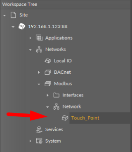
- Then, add an appropriate component from the Modbus library; in this case, the AnalogPoint, which reads the temperature from the Touch Point.
- In the Property Sheet of the added point, fill in a register’s address; in this case, the register responsible for temperature is (dec 300).
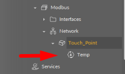
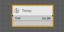
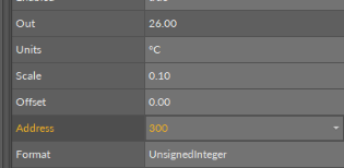
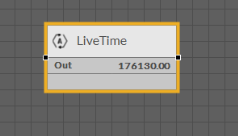
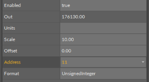
- Similarly to the above example, add a point with a register’s address responsible for the LiveTime (dec 11).
- The last step is to add a point with a register’s address responsible for CO2 measurements (dec 302).
The above examples only scratch the surface of possibilities stemming from connecting the Touch Point with the nano EDGE ENGINE controller. Adding relevant registers and including them in a logic built with components from the iSMA_Control kit allows for creating a lot of different BMS control configurations.
Note: A table with all Modbus registers is available in the Touch Point user manual
The same workflow applies to the ZAC24-IP-D, which is the controller used for zone applications and for TP-ONE.